UN rail gauge insulator is a non-metal fastening component that provides an insulating interface at the rail foot and contributes to the designed rail restraint and gauge-control geometry of the fastening assembly. Correct selection requires matching the component to the rail section, fastening-system designation, and approved drawing so that the specified electrical insulation and rail-clip seating requirements are achieved within the complete fastening assembly.
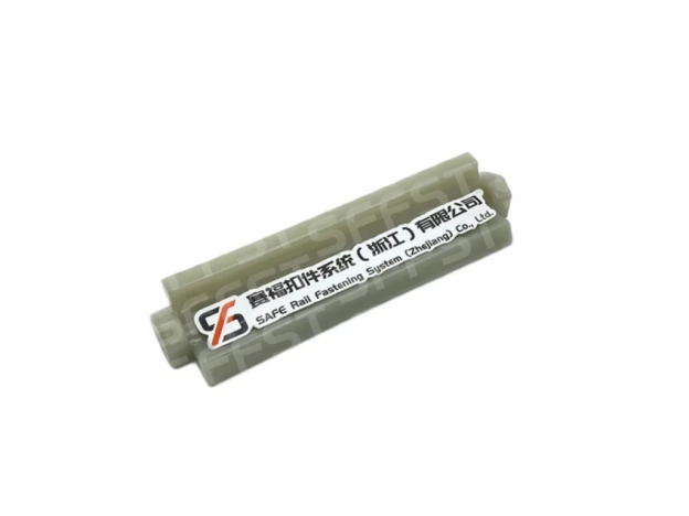
Rail Gauge Insulator Electrical Testing and Wear Checks
Functional Role in the Fastening Assembly
The component is positioned adjacent to the rail foot and interfaces with the rail clip, shoulder, rail pad, and/or baseplate to hold the rail in its intended position. In service, that means local contact forces, limited movement, and repeated operational loading transmitted through the rail and fastening assembly. A rail gauge insulator that may appear visually similar during procurement can behave differently once the rail, clip, and support geometry are in place.
How electrical checks should be interpreted
Electrical performance should be evaluated according to the applicable test specification and defined test boundary. A rail gauge insulator may have its own component-level electrical resistance requirement, while the fastening system may also be subject to a separate system-level electrical resistance requirement. These two values should not be treated as interchangeable.
The relevant acceptance criterion is whether the specified electrical isolation is maintained under the applicable loading, geometry, environmental conditions, and assembly configuration. An electrical measurement is meaningful only when the test configuration, rail section, fastening components, and test boundary are defined and traceable.
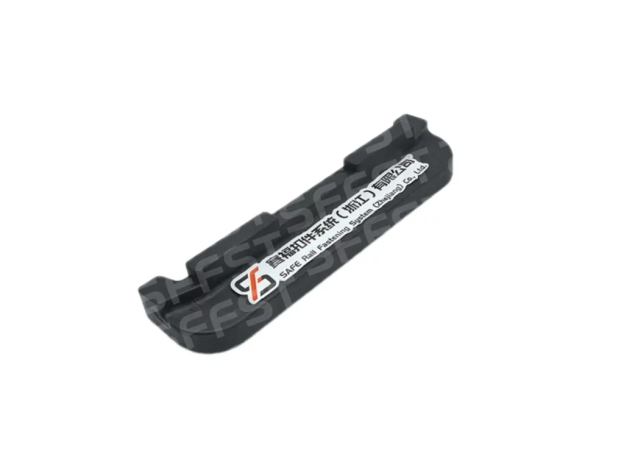
Materials and Geometry
PA66+30%GF and other material families
SFFST identifies PA66+30%GF for rail gauge insulators in specific fastening systems. That material choice gives a defined engineering-plastic base with glass-fiber reinforcement, which is useful where dimensional stability and repeatable molding matter more than a generic resin name. Other systems may use other compounds, so the material should always follow the drawing and the fastening family.
The phrase PA66 glass fiber rail gauge insulator should still be treated as a system-specific material callout, not a universal rule. Material grade, hardness, molding quality, and dimensional requirements should be evaluated against the applicable product specification and fastening-system drawing.
Dimensions, clearance, and seating
Dimensions matter as much as material. The approved drawing should define the rail-foot interface, the clearance for the rail clip, the contact area with the shoulder or baseplate, and any gauge-adjustment relationship with adjacent parts.
The distinction between a rail gauge insulator and a rail gauge baffle is also important during component identification and replacement. A rail gauge baffle may appear in the same product family, but it should not be treated as an interchangeable component or synonym for a rail gauge insulator, because geometry and support function depend on the fastening-system family.
What wear looks like in practice
During field inspection, deterioration of a rail gauge insulator may be identified through cracking, deformation, damaged seating surfaces, excessive clearance, or other changes that affect the designed interface. Acceptance limits should be based on the applicable drawing, maintenance specification, and fastening-system requirements.
For maintenance teams, wear inspection is less about counting scratches and more about checking whether the component continues to provide the specified seating geometry and interface condition. If it no longer seats cleanly against the rail foot or adjacent components, recheck the fastening node before the condition develops into a wider fastening-system defect.
Selecting the Right Rail Gauge Insulator
Match the system before the component
Selection starts with the rail section, sleeper or baseplate, and fastening-system designation. From there, confirm the rail clip, rail pad, and any gauge-adjustment parts, because the insulator only works correctly when its mates are already known.
A match built on the system drawing is more reliable than one built on appearance. The selected insulator should achieve the specified seating and dimensional relationship within the fastening assembly.
Use drawings and acceptance points
For replacement work, compare part number, installation position, approved drawing revision, and bill of materials before removing the existing component from service. That check is more reliable than judging by color or external outline alone.
SFFST Production and Quality Control
Injection molding and consistency
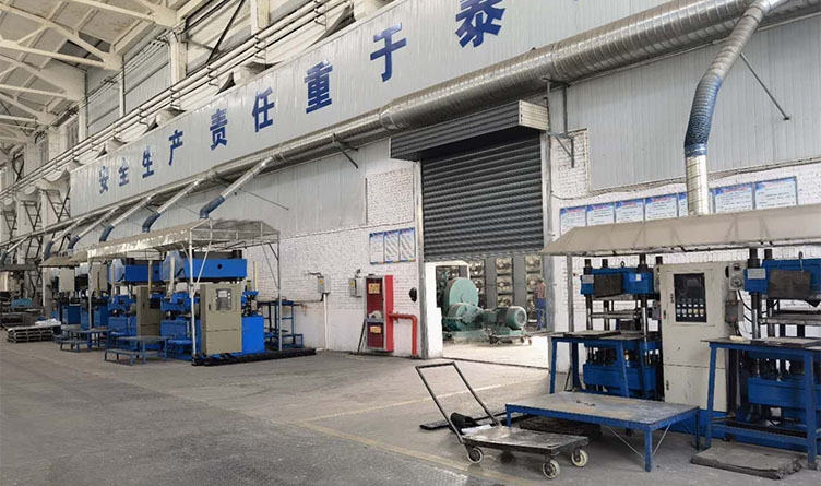
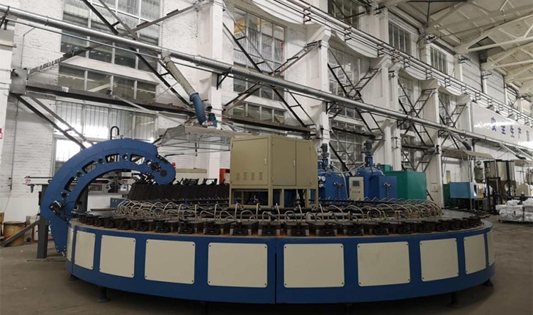
SFFST states that its injection-molding production lines manufacture rail gauge insulators, rail gauge baffles, embedded dowels, and height adjustment pads. For incoming inspection, the molded part should be checked for dimensional conformity, seating-surface condition, cracks, deformation, and molding defects, with acceptance criteria defined by the approved drawing and product specification.
Consistent dimensional geometry is essential for repeatable installation and reliable performance across production batches. The rail-foot seat, clip clearance, and mating surfaces must hold their shape so the fastening system behaves consistently across installation batches.
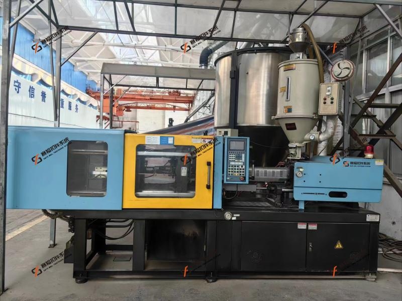
Incoming inspection before installation
Incoming inspection should compare the physical part with the approved drawing and system bill of materials before installation. Check the material grade, part number, drawing revision, dimensions, dimensional tolerances, visual condition, batch identification, traceability records, and applicable inspection documentation.
Conclusion
A rail gauge insulator is a system-specific non-metal fastening component whose material, geometry, wear condition, and electrical role must be evaluated within the complete railway fastening system.
If you are matching a rail gauge insulator to a defined fastening system, review the SFFST product family first and verify the approved drawing before installation. Early verification of system compatibility can reduce the risk of installation errors, component mismatch, and interface-related defects. Contactez-nous dès aujourd'hui Pour en savoir plus.
FAQ
Q: What does a rail gauge insulator do?
A: A rail gauge insulator is a non-metal railway fastening component positioned beside the rail foot. It provides an insulating interface at the rail foot and works with the rail clip, shoulder, rail pad, and other fastening components to achieve the specified rail restraint and assembly geometry.
Q: How is electrical performance checked?
A: Electrical performance should be checked at the correct level, which may be the component, a paired interface, or the complete fastening assembly. The system drawing and acceptance method should define the test boundary. SFFST Type III data, for example, gives system electrical resistance for the complete arrangement, not for a disconnected part alone.
Q: Is a rail gauge insulator the same as a rail gauge baffle?
A: Not necessarily. The terms are not universally interchangeable, and their exact function and geometry depend on the fastening-system family and manufacturer terminology. Always confirm the approved assembly drawing and component specification before assuming that one part can replace the other in the field.
Q: What should be confirmed before replacement?
A: Start with the fastening-system designation and rail profile, then confirm the component specification or part number, installation position, rail-foot interface, clip or tension-clamp type, shoulder or baseplate arrangement, drawing revision, and any gauge-adjustment requirement. The approved drawing should remain the primary reference before any rail gauge insulator is installed.