Choosing between the W14 and W14HH fastening systems requires more than comparing their product names or individual components. Both systems are designed as complete railway fastening assemblies, but their published technical specifications differ in areas such as system clamping force, axle-load conditions, operating speed, and component configuration.
This W14 vs W14HH fastening system comparison examines their components, clamping force, axle-load and speed conditions, gauge adjustment, electrical insulation resistance, pull-out resistance, and other relevant technical parameters. Understanding these differences can help railway engineers, infrastructure owners, and procurement teams evaluate each fastening system against the actual track design, operating envelope, and project requirements.
W14 Fastening System Design and Performance
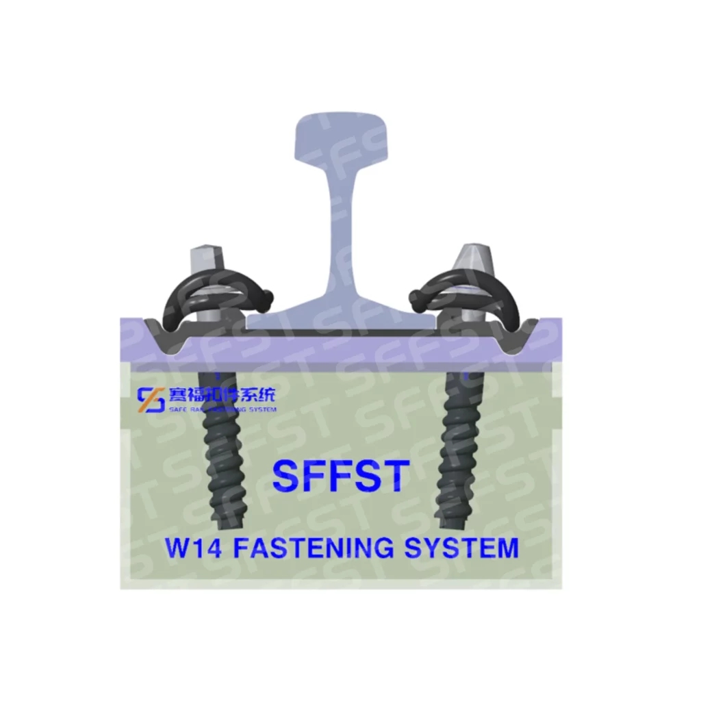
Core components and rail interface
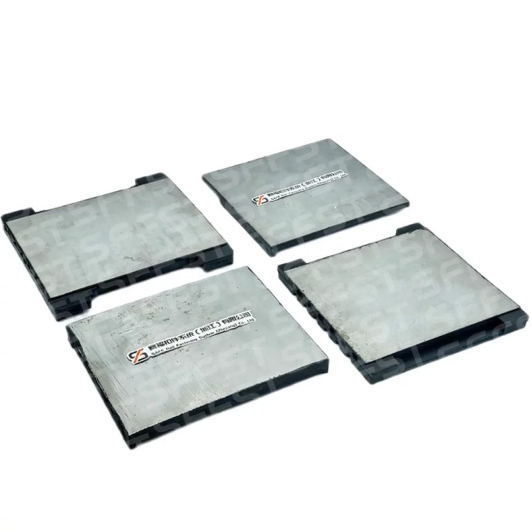
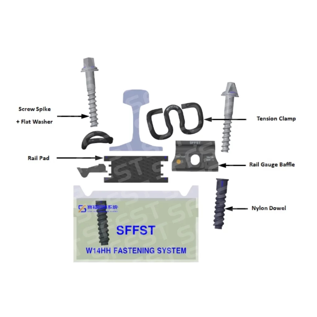
A W14 fastening system combines an SKL 14 tension clamp with Ss35 or DHS35 screw spikes and a ULs7 flat washer. The rail-seat assembly includes a Wfp 14k-12 rail gauge baffle, a Zw687 xx/160/y rail pad, and an Sdu25 embedded dowel. Each component has a defined installation position and functional interface within the fastening assembly.
The rail pad provides the resilient layer beneath the rail, while the gauge baffle supports the lateral interface and helps maintain the specified lateral positioning of the rail within the fastening assembly. The SKL 14 tension clamp provides the elastic clamping force that secures the rail to the fastening assembly. This arrangement is why a replacement part should be matched to the approved system drawing rather than selected solely on the basis of dimensional or visual similarity.
Speed, curve radius, and adjustment range
The given performance parameters for the W14 include the following: maximum axle load of 26 t; minimum curve radius of R150 m; and maximum speed of 250 km/h. System clamp force is not less than 18 kN; gauge adjustment is ±10 mm; electrical resistance is not less than 5 kΩ; and proof load for pull-out resistance is not less than 60 kN.
These standards pertain to the fastening system as a whole and must not be understood as separate performance benchmarks for each component. In the case of use of W14 at speeds and curves of radius listed, designers must ensure that the rail, support system, and curve geometry are properly checked, among other factors, prior to confirmation of applicability. The mentioned gauge adjustment range is possible only if the matching components are properly designed and installed.
W14HH Fastening System: Axle Load and Operating Conditions
System Clamping Force and Load Conditions
The W14HH fastening system uses an SKL 14R tension clamp together with the Ss35 or DHS35 screw spike and the ULs7 flat washer family, as in the W14 system. However, its rail interface is defined by the Wfp 14k 700R-12 HH rail-gauge baffle and an Sdu25 dowel. The specified rail-gauge baffle and rail pad must therefore be included in the complete W14HH fastening configuration.
This distinction is technically significant when comparing W14 and W14HH, because the specified rail-interface components affect the applicable operating envelope of each fastening system.
Heavy-haul compatibility and operating conditions
The data for W14HH includes specifications for axle loads of 26 t and 35 t. The axle load of 35 t is provided with speed up to 160 km/h. Therefore, it cannot be used as a universal classification for all speeds and axle loads. It becomes important when making comparisons between W14HH fastening systems on heavy haul rails and fastening systems designed for other axle load and speed range.
The W14HH system further includes ±10 mm gauge adjustment, an electrical resistance of at least 5 kΩ, and a proof load of at least 60 kN for pull-out resistance. These common figures cannot change the distinction between the clamping force and operating range. For heavy haul operations, the choice of fastening system should start from the axle load, operating speed, radius of the curve, rail type, support arrangement, and maintenance conditions.
W14 vs W14HH Technical Comparison
| Parameter | W14 | W14HH |
| Pince de tension | SKL 14 | SKL 14R |
| Déflecteur de gabarit de rail | Wfp 14k-12 | Wfp 14k 700R-12 HH |
| Plaque de rail | Zw687 xx/160/y | Zw xx/175/y |
| Goujon | Sdu25 | Sdu25 |
| Vis à tête plate | Ss35 / DHS35 | Ss35 / DHS35 |
| Rondelle | ULs7 | ULs7 |
| System Clamping Force | ≥18 kN | ≥23 kN |
| Axle Load | 26 t | 26 t / 35 t |
| Gauge Adjustment | ±10 mm | ±10 mm |
| Résistance électrique | ≥5 kΩ | ≥5 kΩ |
| Pull-out Proof Load | ≥60 kN | ≥60 kN |
| Dual Rail Gauge Expansion | ≤6 mm | ≤6 mm |
SFFST Manufacturing and System Integration
Metal components and fastening consistency
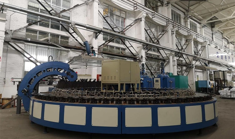
ประวัติความเป็นมาของแบรนด์ describes automated production for tension clamps, spikes, bolts, nuts, and washers, with processes covering forming, heat treatment, surface treatment and corrosion-protection processes, packaging, and warehousing. For W14 and W14HH assemblies, dimensional consistency of the metallic components supports consistent fastening installation, clamp seating, and load transfer. Installation should follow the specified fastening procedure, including the specified screw-spike installation and lubrication requirements.
Rail pads and insulating interfaces
Rail pads, gauge baffles, and dowels are functional components of the fastening assembly and contribute to its mechanical and electrical characteristics. Their geometry, material properties, and installation condition should therefore be controlled as specified for the complete fastening system. SFFST’s non-metal laboratory testing scope includes tensile performance, Shore A hardness, static and dynamic stiffness, fatigue performance, hot-air aging, and insulation resistance.
Conclusion
Le W14 fastening system and W14HH fastening system serve different decision priorities. Both systems require disciplined matching of rail, pad, gauge interface, dowel, clamp, and installation method.
For engineers and asset managers, the appropriate choice should be based on the actual traffic envelope and the complete rail-seat design. Assess W14 and W14HH against the applicable axle load, operating speed, curve radius, rail profile, support configuration, gauge-adjustment requirements, and project-specific acceptance criteria. Use SFFST’s system resources to move from a component decision to a reliable rail interface.
FAQ
Q: Can W14HH be used for every heavy-haul railway?
A: Universal applicability cannot be taken for granted. The W14HH system has a 35 tonne axle load and speeds up to 160 kilometers per hour. However, the entire track system remains the determining factor. Rail section, sleepers, curve radius, fastening pattern, installation process, maintenance issues, and acceptance requirements need to be considered.
Q: What adjustment range is listed for these systems?
A: Rail gauge adjustment for both W14 and W14HH is done ±10mm. This tolerance is applicable to the fastener interface, hence it is to be considered along with the rail gauge baffle or angle guide plate, rail pad, dowel, clip, and supporting geometry. Adjustment is always to be done according to the project drawings.
Q: What should be checked before selecting a W14 fastening system?
A: Verify the wheel load, speed of operation, curve configuration, rail profile, rail fixing method, gauge adjustment, electrical resistance, and pull-out parameters of the rail. Once done, fit together the clamp, screw spike, washer, gauge interaction, rail pad, and dowel into a single unit. This will give the most accurate approach for selecting the W14 rail fastening system.