Railway track components work as a connected load-management system. A typical rail fastening interface can be understood through two related functions: the vertical load path runs from the rail through the rail pad and baseplate or sleeper, while the rail clip or tension clamp provides the required clamping force and restraint to secure the rail. Each layer helps hold the rail, distribute force, control movement, provide insulation, or transition into the supporting structure.
The arrangement varies by fastening system, but the principle remains useful: a rail clip cannot compensate for a misplaced pad, and a strong baseplate cannot correct an unsuitable sleeper interface. SFFST supplies coordinated metal and non-metal fastening components.
The Railway Track Components Load Path
Rail Clip vs Rail Pad vs Rail Baseplate vs Baseplate Pad
The following table summarizes the typical position, primary function, and material options of the main railway fastening components discussed in this article. The exact configuration varies by fastening system, rail section, sleeper type, and project requirements.
| Component | Typical Position | Primary Function | Typical Materials |
| Rail Clip | Engages the rail foot and fastening shoulder | Clamping force and rail restraint | Spring steel |
| Rail Pad | Beneath the rail | Resilience, electrical insulation, load distribution | Rubber, PU, TPE, composites |
| Rail Baseplate | Beneath the rail pad or rail-seat assembly | Load transfer and fastening support | Steel, cast iron |
| Baseplate Pad | Beneath the baseplate where specified | Resilience, insulation, load distribution | Rubber, PU, TPE, composites |
From Rail Contact to Rail Clip
The rail receives wheel-rail forces and transfers them into the fastening zone. The rail clip or tension clamp provides the required clamping force and rail restraint, while the rail pad provides resilient support, electrical insulation, and controlled vertical stiffness at the rail-seat interface. Its working condition depends on rail geometry, clip position, support height, bolt or shoulder arrangement, and the resilient layers beneath it.
SFFST product groups include Rail Clip, Tension Clamp, K-type Clip, and Nabla Blade. They are related, not automatically interchangeable. Selection follows the named fastening system and rail-seat geometry rather than a clip’s visual shape.
From Rail Pad to Railroad Base Plate
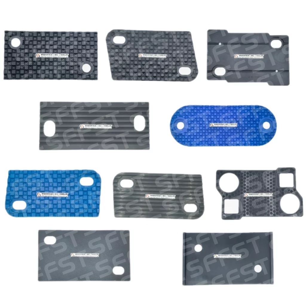
A rail pad is installed beneath the rail, either between the rail and a rail baseplate or directly between the rail and sleeper, depending on the fastening system. They provide an elastic, insulating interface while helping spread contact pressure and control dynamic loads and vibration transmission. A rail baseplate provides a rigid load-transfer and fastening platform between the rail fastening assembly and the sleeper. The baseplate transfers and distributes loads from the rail fastening assembly to the sleeper or supporting structure. Its outline, shoulders, holes, slots, and bearing area must align with the pad and hardware. If the pad footprint, thickness, stiffness, or position does not meet the fastening-system requirements, the baseplate may experience non-uniform support and localized contact pressure.
How Each Component Supports the Track
Rail Clips and Controlled Restraint
A rail clip provides clamping force and contributes to the vertical and lateral restraint of the rail, helping maintain the designed rail position under operational loading. Its geometry, toe position, clamping force, and installation condition must be compatible with the rail section, rail pad thickness, fastening shoulder, bolts, and other system-specific components.
If the clip is not seated correctly, the system may lose restraint or develop concentrated contact. Clip selection, installation, and inspection should therefore be considered with rail pads and baseplates.
Rail Pads and Baseplate Pads
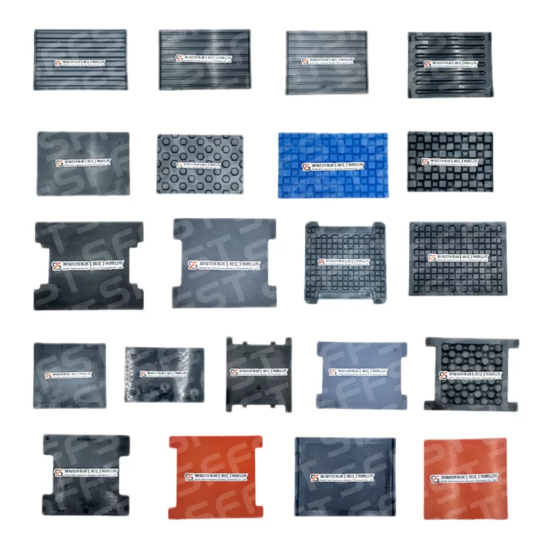
Rail pads are non-metal components positioned between the rail and its support. SFFST identifies rubber, polyurethane, thermoplastic elastomer, and composite materials for rail pads, with customized specifications available. Their properties may contribute to vibration and noise attenuation depending on material properties, stiffness, and track-system design.
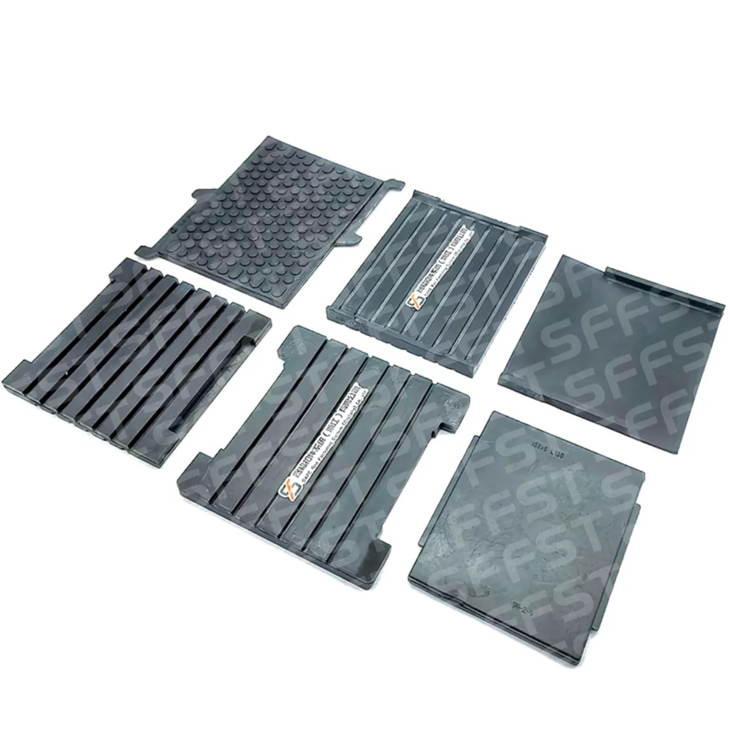
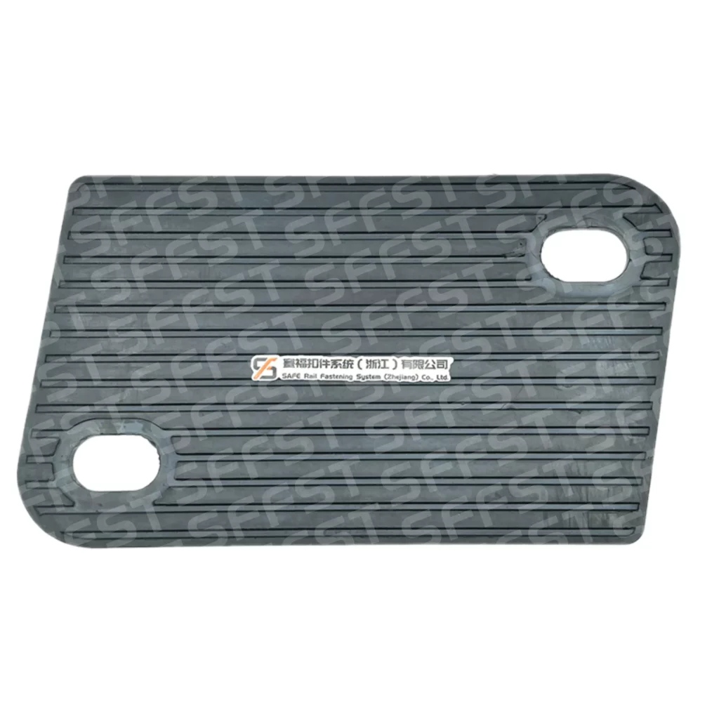
Baseplate pads occupy a different interface: between the baseplate and sleeper or supporting structure. They provide an elastic and insulating layer below the baseplate. Confusing the two products can create an incorrect load path because the rail pad responds directly beneath the rail, while the baseplate pad supports the whole baseplate footprint.
Why the Baseplate and Sleeper Interface Matters
Baseplate Support and Load Distribution
The rail baseplate spreads fastening-zone load and connects the rail assembly to the sleeper. The baseplate pad can help reduce localized contact pressure and moderate load transmission to the sleeper, subject to its specified stiffness and system design. The result depends on contact, thickness, and compatibility with edges and fixing points.
A rigid plate with incomplete support can transfer force through a small contact zone, increasing local pressure or movement. The answer is not automatically a thicker pad; material, footprint, stiffness, and fastening-system design must be reviewed together.
Insulation, Gauge Control, and Alignment
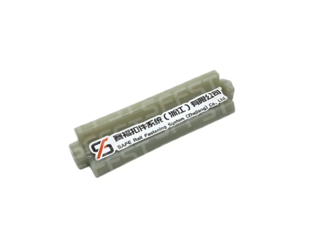
A fastening assembly may also include rail gauge insulators, rail gauge baffles, bolts, nuts, washers, dowels, and height adjustment pads. These parts help maintain rail position, separate conductive paths, and control the rail-baseplate-sleeper relationship. Because these components have different mechanical, dimensional, and electrical requirements, one pad type should not be substituted for another without verifying system compatibility.
Track gauge and rail elevation are system-level parameters determined by the combined geometry and tolerances of the rail, fastening components, pads, baseplate, and sleeper interface. The clip, insulators, pads, baseplate, and sleeper must share the same reference geometry. A visually fitting component that changes rail elevation or clip range may create an alignment problem.
What Happens When a Component Fails
Rail Clip Loosening or Fatigue
A loose or fatigued rail clip can reduce restraint and allow greater rail movement. Potential effects include increased lateral or longitudinal rail movement, loss of clamping force, abnormal contact marks, and increased loading on adjacent fastening components. The cause may be the clip, installation, changed pad thickness, or damaged support.
Pad Wear, Baseplate Movement, and Sleeper Stress
A worn or displaced rail pad can change rail-seat contact and reduce separation between metal components. A damaged baseplate pad can create uneven support, localized pressure, or movement, passing a less balanced load pattern to the sleeper.
Failure review should follow the load path rather than replacing the most visible part first. Inspect the clip, rail pad, baseplate, baseplate pad, bolts, insulators, sleeper contact, and contamination as one interface.
How SFFST Connects the Component Product Cluster
Metal Fastening Components
SFFST railway fastening products include clips, tension clamps, bolts, nuts, washers, spikes, baseplates, and other metal components. Production information covers clip and tension-clamp forming, heat treatment, surface treatment, corrosion protection, packaging, and storage. This manufacturing chain is relevant because metal components must keep their geometry and surface condition through repeated service.
Non-Metal and Casting Components
The same fastening assembly may use rail pads, baseplate pads, resilient tie pads, height adjustment pads, rail gauge insulators, rail gauge baffles, dowels, and other non-metal or cast components. SFFST production lines include polyurethane pouring, rubber mixing and vulcanization, injection molding, and related processes for these component groups.
Selection and Inspection Considerations
Match the System Before the Part
Begin with the fastening-system reference, rail section, sleeper type, baseplate arrangement, load environment, and electrical requirement. Then confirm each component’s position and function. Rail pads, baseplate pads, and under sleeper pads occupy different locations and need different specifications.
For new designs, review the controlled assembly drawing and material requirements. For replacement work, compare the existing part with the current revision and record wear, compression, cracking, corrosion, contamination, and movement. This helps SFFST identify a replacement or broader interface review.
Use Testing and Application Context
Metro, heavy-haul, high-speed, conventional, depot, and industrial tracks impose different loads, exposure, and maintenance demands. SFFST laboratory resources include abrasion, aging, hardness, tensile, fatigue, impact, insulation, and fastening-resistance testing. Selection should connect the test method with the actual component and application.
Conclusion
Railway track components perform best when the load path is treated as one engineered interface. The rail clip controls restraint, rail pads provide an elastic rail-seat layer, the railroad base plate distributes support, the baseplate pad manages the lower interface, and the sleeper transfers load into the track structure. A failure in one layer can change demand on the others.
Need Reliable Railway Fastening Components?
From rail clips and tension clamps to rail pads, baseplates, and baseplate pads, SFFST provides coordinated fastening components designed for different rail sections, sleepers, load conditions, and operating environments.
Contact SFFST today to discuss your railway fastening requirements and find the right component or complete fastening-system solution for your project.
FAQ
Q: What is the function of a rail clip in a fastening system?
A: A rail clip helps hold the rail in position and contributes to vertical and lateral restraint. Its working behavior depends on the rail section, clip geometry, pad thickness, shoulder or bolt arrangement, and installation condition. It should be selected as part of the fastening system rather than treated as an isolated clamp.
Q: How do rail pads and baseplate pads differ?
A: A rail pad is placed directly beneath the rail and above its immediate support. A baseplate pad is placed beneath the baseplate and above the sleeper or supporting structure. Both may provide elasticity and insulation, but they serve different contact planes, footprints, stiffness requirements, and inspection points.
Q: What is the role of a railroad base plate?
A: A railroad base plate, commonly called a rail baseplate in technical documentation, provides a support and connection platform for the rail fastening assembly. It spreads load toward the sleeper and works with the rail pad, baseplate pad, clips, bolts, and insulators to maintain the intended rail position.
Q: What can happen when a rail fastening component fails?
A: Failure can change restraint, rail position, contact pressure, insulation, or load distribution. A loose clip, worn rail pad, displaced baseplate pad, or damaged fixing may increase demand on adjacent parts. Inspection should follow the complete load path before deciding whether one component or the wider interface needs attention.