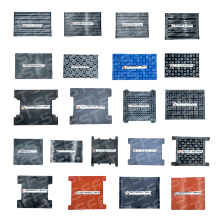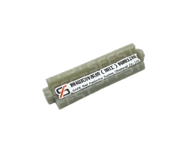
Rail pad dimensions should be determined from the rail-seat geometry, fastening-system interface, and project-specific performance requirements rather than from product photographs. Before selection, confirm the rail foot, support footprint, hole and slot clearances, thickness, stiffness, electrical requirements, and drawing tolerance. This helps SFFST match rail pads, baseplate pads, and rail adjustment pads to the track assembly.
A similar-looking pad can perform differently because a few millimeters can change clip clearance, rail height, compression, or load distribution. Measure the interface first, then use the fastening drawing and verified system data to define the pad.
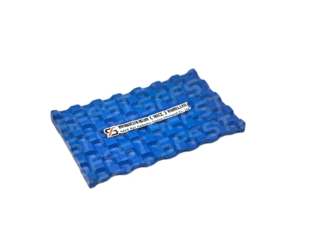
Rail Pad Dimensions Start With Component Position
Rail Pads Sit at the Rail Support Interface
Rail pads are installed between the rail foot and the rail-supporting surface, such as a sleeper or baseplate, depending on the fastening-system configuration. Their length and width should cover the intended rail-seat contact area without blocking clips, bolts, shoulders, drainage paths, or electrical separation features.
SFFST identifies rubber, polyurethane, thermoplastic elastomer, and composite materials for rail pads, with specifications available for customization. Material properties and dimensional requirements should be specified together because thickness, stiffness, compression behavior, and electrical resistance collectively affect fastening-system performance.
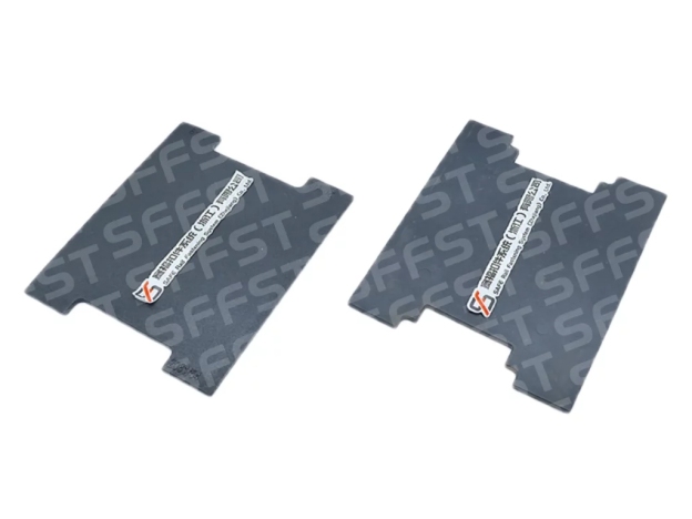
Baseplate Pads Use a Different Footprint
Baseplate pads sit between the baseplate and sleeper or supporting structure. Their outline is governed primarily by the baseplate footprint and fastening-system clearance requirements. Where applicable, bolt or anchor locations, recesses, shoulders, slots, and edge distances must also be incorporated into the drawing. A rail pad drawing cannot automatically be reused as a baseplate pad drawing.
The first drawing review should identify each relevant contact surface and interface: rail-to-pad, pad-to-baseplate, and baseplate-to-sleeper. This prevents measuring the visible assembly instead of the surface that compresses the pad.
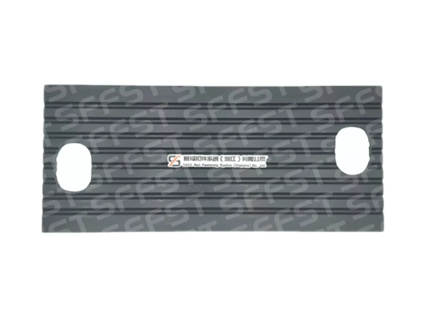
What to Measure Before Choosing Rail Pads
Rail Foot and Support Footprint
Measure the rail-foot geometry of the installed rail section and record the required rail-seat bearing width. The pad geometry should maintain the required clip and fastener clearances and provide the specified rail-seat bearing area defined by the fastening-system drawing. Record both the longitudinal rail-seat length and transverse width.
Baseplate Edges, Holes, and Clip Clearance
For a baseplate pad, record baseplate length and width, corner geometry, bolt or anchor positions, hole diameters, slot directions, and clip or tool clearance. Holes, slots, cut-outs, and edge relief must come from the fastening drawing, not a photograph.
Use one coordinate origin, such as the rail or baseplate centerline. Hole centers, slot ends, edge distances, and orientation marks can then reference the same datum, making revisions easier.
How Thickness, Stiffness, and Tolerance Work Together
Thickness Is Not the Same as Static Stiffness
Thickness affects rail height and compression travel, but does not define pad performance alone. SFFST system information shows that static stiffness varies by configuration.
Tolerance and Rail Height Adjustment
The drawing should distinguish nominal thickness from allowable tolerance and state whether the dimension is measured free, compressed, or after bonding. Otherwise, a pad may meet the nominal value but change rail height or clip working range.
Fastening System Data Changes the Pad Specification
Material, Hardness, and Insulation Requirements
The requirement depends on the fastening system, signaling arrangement, and material. State the material family, hardness method, and electrical test condition when required.
Dynamic-to-static stiffness ratio is also system-dependent. Record it beside the dimensional callouts rather than assuming a thicker pad provides better isolation.
System References Are Not Universal Dimensions
A fastening system may assign separate part numbers or drawing references to the rail pad, baseplate, baseplate pad, and height adjustment pad. Fastening-system component codes and drawing references are manufacturer- and system-specific. Do not infer pad dimensions from a partial or placeholder code. These connect components within the system but do not provide universal dimensions or tolerances.
How to Mark a Rail Pad Drawing
A Practical Dimension Callout Template
A drawing note can use this template: overall length L by width W by nominal thickness t; rail-seat contact width; where applicable, hole or slot type, location, and positional tolerance; edge distance; clip clearance; orientation; material; hardness; static stiffness; electrical resistance; and feature tolerances. This is a documentation template, not a universal SFFST size.
Use separate datums for the rail centerline, baseplate centerline, and fastening direction where needed. Mark top and bottom faces when texture, coating, bonding, or friction differs. If asymmetric, add an orientation arrow and installation side.
Avoiding Photo-Based Dimension Errors
A product photo cannot show true scale, compression, hidden slots, or rail-clip clearance. It may show a prototype, another fastening system, or an angled view. Use photos for identification only, then confirm geometry against the drawing and measured interface.
A technical package should include rail section, fastening-system name, sleeper or baseplate type, application load, environment, drawing revision, material, and dimensions that are fixed versus open for confirmation. This gives SFFST a usable starting point without inventing missing data.
A Pre-Selection Checklist for SFFST Pad Solutions
Track and Fastening Information
Before sending a package, check rail profile, rail-foot width, fastening reference, baseplate outline, sleeper type, pad location, rail-height target, gauge-adjustment range, load classification, signaling or insulation requirement, and orientation. Identify whether the part is new, replacement, or revised.
Separate rail pads, baseplate pads, and rail adjustment pads instead of using one generic term. Their positions and functions differ, so the drawing, material requirement, and acceptance criteria should differ too.
Testing and Revision Control
SFFST laboratory resources include equipment for non-metallic material evaluation, abrasion, aging, Shore hardness, universal tensile testing, and track-fastener resistance. SFFST laboratory resources can support a link between pad specifications and test methods, while referencing applicable standards.
Finish with a revision number, datum scheme, tolerance table, material designation, test references, and open points. This reduces comparison between an outdated pad drawing and a current assembly.
Conclusion
Rail pad dimensions should follow the rail seat, baseplate or sleeper footprint, clip and bolt clearances, thickness tolerance, stiffness target, and electrical requirement. For baseplate pads or rail adjustment pads, define the contact plane first, then control geometry and performance.
Need rail pads matched to a specific fastening system? SFFST can help you verify rail pad dimensions, thickness, stiffness, tolerances, and material requirements based on your technical drawings and application conditions. Send us your rail profile, fastening-system reference, existing pad dimensions, or drawing revision, and our team can help identify a suitable rail pad, baseplate pad, or height adjustment pad solution.
Contact SFFST today to discuss your rail fastening pad requirements and request a customized technical solution.
FAQ
Q: What is the difference between a rail pad and a baseplate pad?
A: A rail pad is installed between the rail and its immediate support, such as a baseplate or sleeper. A baseplate pad is installed below the baseplate and above the sleeper or supporting structure. Their contact surfaces, clearances, stiffness targets, and drawing datums can therefore be different.
Q: How should rail pad thickness be checked?
A: Check nominal thickness, allowable tolerance, measurement condition, compression state, bonding layers, and the assembled rail-height requirement. Confirm the value against the fastening-system drawing rather than measuring only the visible edge. Replacement work should also record the condition of the existing pad and any added shims.
Q: What dimensions should be shown on a rail pad drawing?
A: Overall length and width, nominal thickness, thickness tolerance, datum references, contact area, cut-outs or holes where applicable, material, hardness, stiffness, electrical resistance, and applicable test standards.